VTEC system — description and component checks
General description
1. The VTEC system has the capability of being able to continuously change the valve lift and timing — not just above a certain engine speed. The VTEC uses three different intake cam lobe profiles and two exhaust cam lobes for each cylinder. It is also equipped with a rocker arm oil control valve, and a rocker arm oil pressure switch that works with the ECM/ PCM and EGR valve, which alters the phasing of the secondary rocker arms to yield maximum potential power output and proper emissions for any given engine speed. For more information on the VTEC system, see Emissions and engine control systems.
2. The differences between conventional engines and the VTEC-equipped engines are strictly in the components and operation of the valve train.
3. The engine management computer has the ability to physically change which camshaft intake lobes are being used to operate the intake valves. The computer turns the system ON or OFF, depending on sensor input.
4. The PGM-FI engine management system relies on information from the vehicle speed sensor (vehicle speed), CKP sensor (engine speed), throttle position sensor (throttle angle), coolant temperature sensor (coolant temperature) and the MAP sensor (engine load).
5. The camshaft has two different intake valve lobe profiles (lift and duration specifications).
6. At low speeds, the secondary intake valve operates on its own camshaft lobe, which has lift and duration profiles designed specifically for the low-end torque and responsiveness. The opening (valve duration) is intended to be just enough to keep atomized
fuel from puddling at the valve head. This limited valve operation is designed to provide good low-end torque and responsiveness, by inducing swirl in the combustion chamber from the primary intake valve, which operates with a normal profile.
7. When performance is needed, the primary and secondary rocker arms are locked together through the use of an electrically controlled hydraulic system. Hydraulically operated synchronizing pistons lock two rocker arms together. When activated, the intake valves open to the higher lift and duration of the rocker arm, which has its own camshaft lobe designed with the higher lift profile.
Note: Refer to this Chapter’s Specifications for the camshaft lobe lift dimensions.
Component checks
Note: The VTEC system requires specialized diagnostic equipment to access the on-board computer to test the electrical circuits, actuators and sensors. However, there are some mechanical tests of the VTEC system that the home mechanic can perform to check for obvious and simple problems within the system. Have the VTEC system diagnosed by a dealer service department or other qualified automotive repair facility. Also, some checks and inspections of the VTEC components require removal of the rocker arm assembly (see Rocker arm assembly — removal, inspection and installation).
Rocker arm oil control valve
Note: Most common problems in the VTEC system are associated with the rocker arm oil control valve and its filter. Regular engine oil and filter changes are necessary for trouble-free operation of the valve.
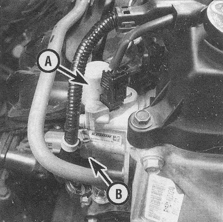
8. The rocker arm oil control valve is located on the right end of the cylinder head, on the firewall side (see illustration). The rocker arm oil pressure switch is located just below the solenoid valve.
i.8 Rocker arm oil control valve (A) and rocker arm oil pressure switch (B)
9. Remove the rocker arm oil control valve (see Emissions and engine control systems) and check the filter 0-ring for clogging. Clean and reinstall with a new 0-ring. A clogged filter screen is often the cause of system problems.
Note: The filter is part of the gasket.
Rocker arms
10. Position the number one piston at Top Dead Center (see Top Dead Center TDC) for number one piston — locating). Remove the valve cover (see Valve cover — removal and installation).
11. Press on the secondary intake rocker arm(s) for cylinder number 1 to see that it moves independently of the primary intake rocker arm. Check the rockers for the other cylinders at their own TDC positions.
Synchronizing assembly
12. Once the rocker arm assemblies have been removed and disassembled (see Rocker arm assembly — removal, inspection and installation), separate the rocker arms and synchronizing components.
VTEC components:
- Primary rocker arm
- Secondary rocker arms, one for each
- Synchronizing pistons
13. Inspect the timing spring, making sure it’s not broken or collapsed. Replace it if necessary.
14. Inspect all other parts (rocker arms and rocker arm pistons) for wear, galling, scoring or signs of overheating (bluish in color) (see illustration 8.12). Use your finger to push on the rocker arm pistons to check for smooth movement. Replace any parts, if necessary.
15. Reassemble each cylinder’s components and wrap a rubber band around the rocker arms before trying to assemble them on the rocker shaft (see Rocker arm assembly — removal, inspection and installation).