Camshafts and rocker arms — removal, inspection and installation
Note: The camshaft holders, the camshafts and the rocker arm assembly are bolted to the cylinder head as one complete assembly. After the assembly is removed from the cylinder head, the different components can be separated on the workbench.
Removal
1. Disconnect the cable from the negative battery terminal (see Engine electrical systems).
2. Position the number one piston at Top Dead Center on the compression stroke for no. 1 cylinder (see Top Dead Center (TDC) for number one piston — locating).
3. Remove the valve cover (see Valve cover — removal and installation).
4. Remove the timing chain (see Timing chain and sprockets — removal, inspection and installation).
5. Loosen all of the rocker arm adjusting screws.
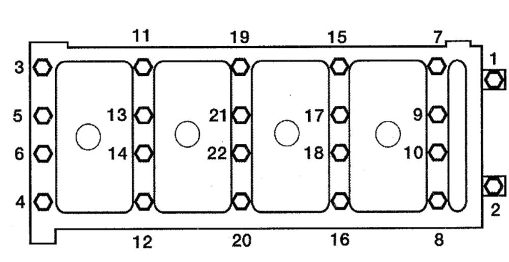
6. Remove the camshaft holder bolts. Follow the correct sequence (see illustration).
i.6 Camshaft holder bolt loosening sequence
7. Remove the upper timing chain guide.
8. Lift the camshaft holders and camshafts off the rocker arm assembly. Remove the rocker arm assembly. Install each bolt into the original camshaft holder for correct reassembly.
Caution: If the intake camshaft sprocket (VTC actuator) is removed from the camshaft and reused later, be sure to store the intake sprocket properly. First, seal the advance holes and the retard hole on the number 1 camshaft journal with tape. Next, punch a hole in the tape over one of the advance holes and blow compressed air through the opening to release the lock. Double-check that the sprocket moves freely in the advance and retard positions.
Inspection
Rocker arm assembly
9. If you wish to disassemble and inspect the rocker arm assembly (a good idea as long as you have them off), remove the retaining bolts and slip the rocker arms, springs, collars and bearing caps off the shafts. Mark the relationship of the shafts to the bearing caps and keep the components in order. They must be reassembled in the same positions they were removed from.
Caution: It is a good idea to bundle the intake rocker arms together with rubber bands.
10. Thoroughly clean the components and inspect them for wear and damage. Check the rocker arm faces that contact the camshaft and the rocker arm tips. Check the surfaces of the shafts that the rocker arms ride on, as well as the bearing surfaces inside the rocker arms, for scoring and excessive wear. Replace any parts that are damaged or excessively worn. Also, make sure the oil holes in the shafts are not plugged.
Camshaft endplay and runout
11. To check camshaft endplay:
- Install the rocker shaft holders, the camshafts and the camshaft holders and follow the correct torque sequence (see Step 20).
- Mount a dial indicator on the cylinder head with the pointer resting on the camshaft nose.
- Using a large screwdriver as a lever at the opposite end, move the camshaft forward-and-backward and note the dial indicator reading.
- Compare the reading with the endplay listed in this Chapter’s Specifications.
- If the indicated reading is excessive, either the camshaft or the cylinder head is worn. Replace parts as necessary.
12. To check camshaft runout:
- With the camshafts on the workbench, support the camshaft with a pair of V-blocks and set up a dial indicator with the plunger resting against the center bearing journal on the camshaft.
- Rotate the camshaft and note the indicated runout.
- Compare the results to the camshaft runout listed in this Chapter’s Specifications this Chapter’s Specifications.
- If the indicated runout exceeds the specified runout limit, replace the camshaft.
Camshaft lobe height
13. Check the camshaft bearing journals and caps for scoring and signs of wear. If they are worn, replace the camshaft holders and rocker arm assembly with a new or rebuilt assembly.
14. Check the cam lobes for wear:
- Check the toe and ramp areas of each cam lobe for score marks and uneven Also check for flaking and pitting.
- If there’s wear on the toe or the ramp, replace the camshaft, but first try to find the cause of the wear. Look for abrasive substances in the oil and inspect the oil pump and oil passages for blockage. Lobe wear is usually caused by inadequate lubrication or dirty oil.
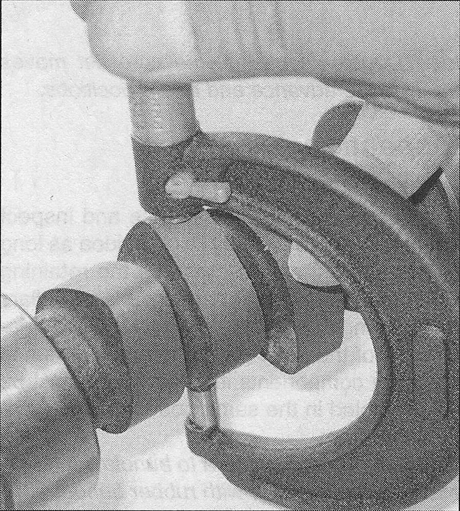
- Using a micrometer, measure the cam lobe height (see illustration), if lobe wear is indicated, replace the camshaft.
i.14 Measure the camshaft lobe height with a micrometer
15. If any of the conditions described above are noted, the cylinder head is probably getting insufficient lubrication or dirty oil. Make sure you track down the cause of this problem (low oil level, low oil pump capacity, clogged oil passage, etc.) before installing a new cylinder head, camshaft or rocker arm assembly.
Installation
16. Lubricate all components with engine assembly lubricant or engine oil and reassemble rocker arms onto the shafts.
17. When installing the rocker arms, shafts and springs, note the markings and the difference between the left and right side components.
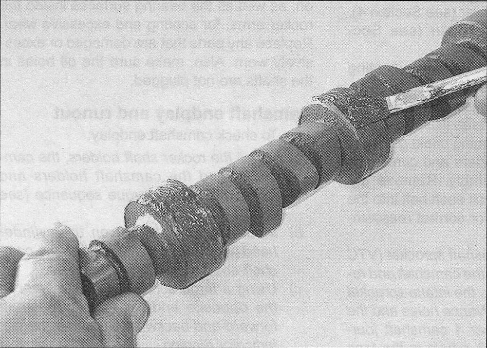
18. Coat the camshaft lobes and journals with camshaft installation lubricant (see illustration).
i.18 Be sure to apply camshaft installation lubricant to the lobes and bearing journals before installing the camshaft
19. Make sure the camshaft sprocket timing marks face up and set the camshafts in the rocker shaft holders.
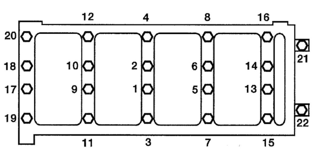
20. Tighten the camshaft holder bolts a little at a time, in the proper sequence (see illustration), to the torque listed in this Chapter’s Specifications.
i.20 Camshaft holder bolt tightening sequence
21. The remainder of installation is the reverse of removal. Adjust the valve clearances (see Tune-up and routine maintenance).
22. Run the engine and check for oil leaks and proper operation.