Rocker arm assembly — removal, inspection and installation
Removal
1. Remove the engine cover (see illustration 4.2).
2. Remove the valve cover (see Valve cover — removal and installation).
3. Position the number one piston at Top Dead Center (see Top Dead Center TDC) for number one piston — locating).
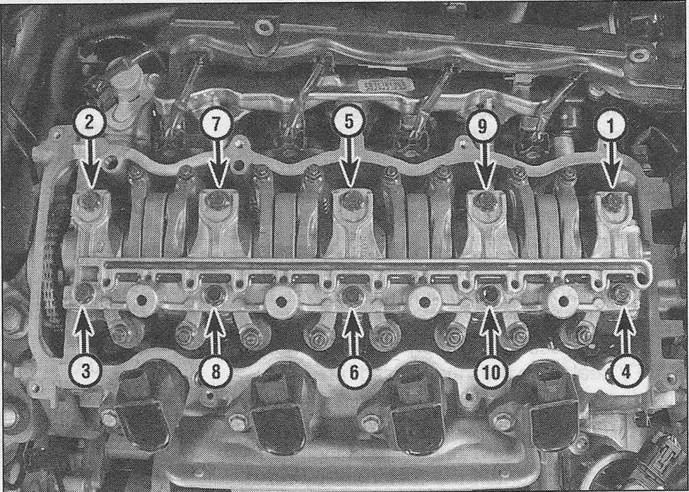
4. Loosen the rocker arm/lost motion holder bolts one turn at a time, in the correct order, until the spring pressure is relieved. Follow the reverse of the tightening sequence (see illustration 15).
5. Lift the lost motion holder and lost motion assemblies off of the rocker arm assembly.
6. Lift the rocker arms and shaft assembly from the cylinder head.
Oil control orifice
7. Pull the orifice from the cylinder head (see illustration 8.12).
Note: There is a 0-ring on the lower section of the oil control orifice that must be replaced once it’s removed.
Inspection
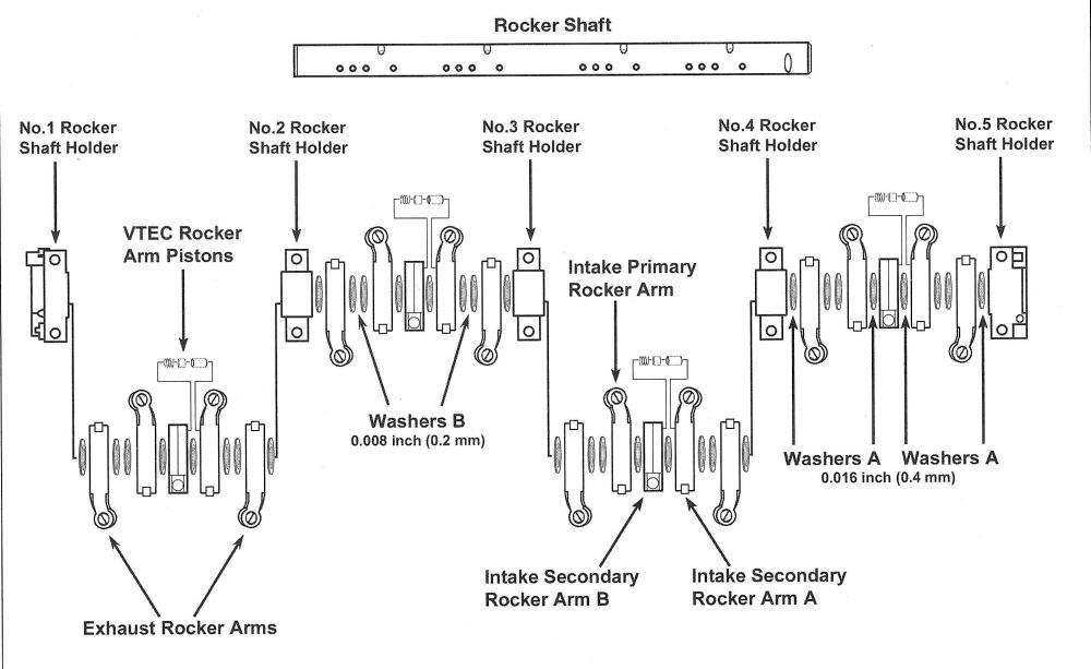
8. If you wish to disassemble and inspect the rocker arm assembly (a good idea as long as you have them off), remove the retaining bolts and slip the rocker arms, springs, collars and bearing caps off the shafts. Mark the relationship of the shaft(s) to the bearing caps or rocker shaft holders and keep the components in order. They must be reassembled in the same positions they were removed from. Caution: The rocker arm pistons, located between the secondary intake rocker arms, are spring loaded and can come apart once they are removed from the rocker arm shiftily is a good idea to bundle the rocker arms together with rubber bands.
9. Thoroughly clean the components and inspect them for wear and damage. Check the rocker arm faces that contact the camshaft and the rocker arm tips. Check the surfaces of the shafts that the rocker arms ride on, as well as the bearing surfaces inside the rocker arms, for scoring and excessive wear. Replace any parts that are damaged or excessively worn. Note: If any one of the secondary rocker arms is damaged, it must be replaced as an assembly. Make sure the oil holes in the shafts are not plugged.
10. Clean the orifice so there are no obstructions and oil flows freely through the orifice.
Installation
11. Lubricate all components with engine assembly lubricant or engine oil and reassemble rocker arms on to the shafts. When installing the rocker arms, shafts and springs, note the markings and the difference between the left and right-side components (see illustration).
i.11 Exploded view of the rocker arms and shafts
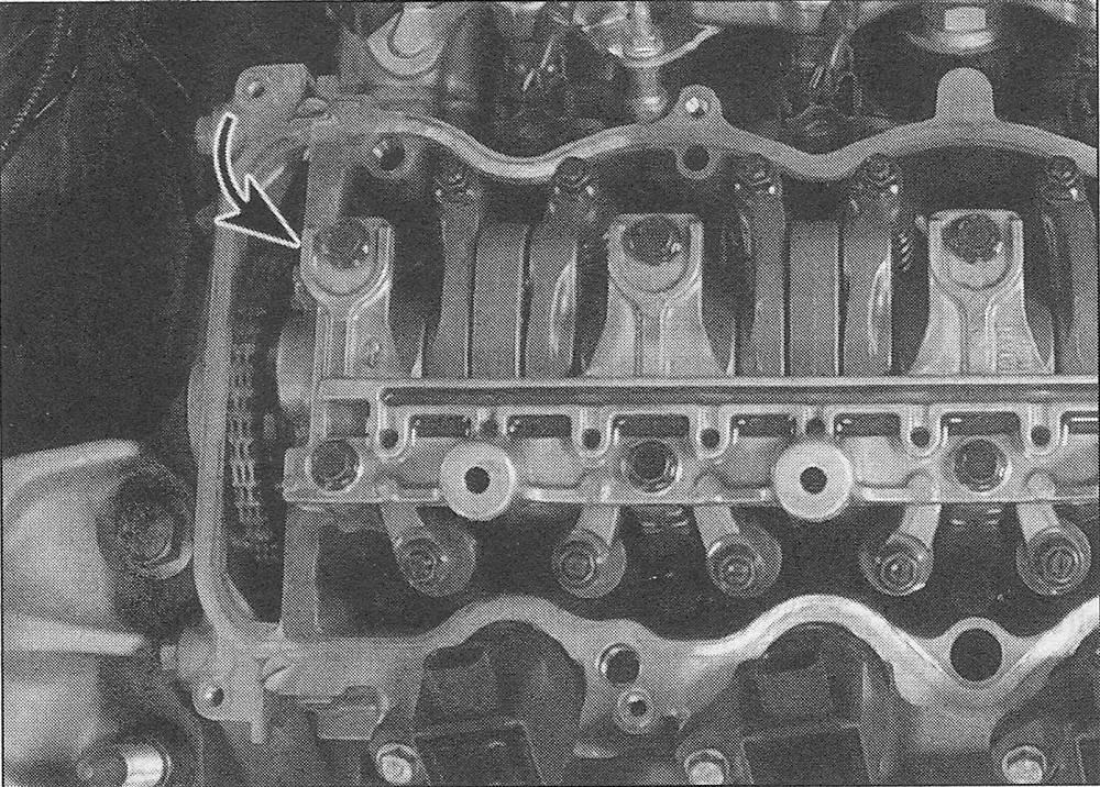
12. Replace the 0-ring on the oil control orifice, then install the orifice in the cylinder head (see illustration).
i.12 The oil control orifice and 0-ring are located at the right end of the cylinder head, under the No. 1 rocker shaft holder
13. Install the rocker arm assembly on the cylinder head.
14. Place the lost motion assemblies into the holder, then install the lost motion holder on the rocker assemblies and tighten the outer two motion holder bolts to the torque listed in this Chapter’s Specifications.
15. Tighten all the rocker arm/lost motion holder mounting bolts a little at a time, in the proper sequence (see illustration) to the torque listed in this Chapter’s Specifications.
i.15 Rocker arm and lost motion holder assembly bolt TIGHTENING sequence
16. The remainder of installation is the reverse of removal. Check and, if necessary, adjust the valve clearance (see Tune-up and routine maintenance).
17. Run the engine and check for oil leaks and proper operation.