Clutch components — removal, inspection and installation
Warning: Dust produced by clutch wear is hazardous to your health. DO NOT blow it out with compressed air and DO NOT inhale it. DO NOT use gasoline or petroleum-based solvents to remove the dust. Brake system cleaner should be used to flush the dust into a drain pan. After the clutch components are wiped clean with a rag, dispose of the contaminated rags and cleaner in a covered, marked container.
Removal
1. Access to the clutch components is normally accomplished by removing the transaxle, leaving the engine in the vehicle. If the engine is being removed for major overhaul, check the clutch for wear and replace worn components as necessary. However, the relatively low cost of the clutch components compared to the time and trouble spent gaining access to them warrants their replacement anytime the engine or transaxle is removed, unless they are new or in near-perfect condition. The following procedures are based on the assumption the engine will stay in place.
2. Remove the transaxle from the vehicle (see Manual transaxle). Support the engine while the transaxle is out. Preferably, an engine support fixture or a hoist should be used to support it from above.
3. The clutch fork and release bearing can remain attached to the transaxle housing for the time being.
4. To support the clutch disc during removal, install a clutch alignment tool through the clutch disc hub.
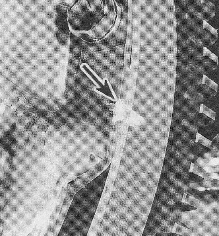
5. Carefully inspect the flywheel and pressure plate for indexing marks. The marks are usually an X, a 0 or a white letter. If they cannot be found, scribe or paint marks yourself so the pressure plate and the flywheel will be in the same alignment during installation (see illustration).
i.5 Mark the relationship of the pressure plate to the flywheel (if you’re planning to re-use the old pressure plate)
6. Turning each bolt a little at a time, loosen the pressure plate-to-flywheel bolts. Work in a crisscross pattern until all spring pressure is relieved. Then hold the pressure plate securely and completely remove the bolts, followed by the pressure plate and clutch disc.
Inspection
7. Ordinarily, when a problem occurs in the clutch, it can be attributed to wear of the clutch driven plate assembly (clutch disc). However, all components should be inspected at this time.
8. Inspect the flywheel for cracks, heat checking, grooves and other obvious defects. If the imperfections are slight, a machine shop can machine the surface flat and smooth, which is highly recommended regardless of the surface appearance. Refer to Chapter 1.8L single overhead camshaft (SOHC) engine for the flywheel removal and installation procedure.
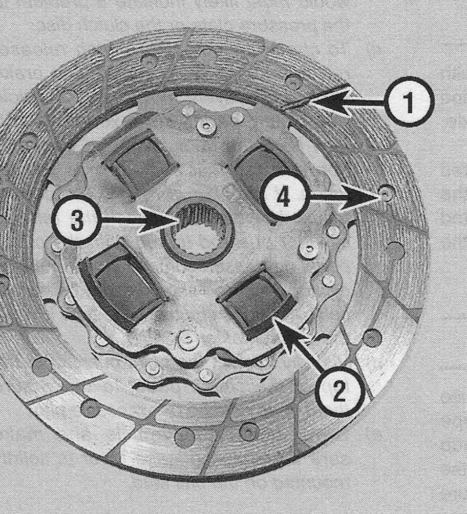
9. Inspect the lining on the clutch disc. There should be at least 1/16-inch of lining above the rivet heads. Check for loose rivets, distortion, cracks, broken springs and other obvious damage (see illustration). As mentioned earlier in this Section, ordinarily the clutch disc is routinely replaced, so if in doubt about the condition, replace it with a new one.
i.9 The clutch disc
1 Lining — this will wear down in use
2 Springs or dampers — check for cracking and deformation
3 Splined hub — the splines must not be worn and should slide smoothly on the transmission input shaft splines
4 Rivets — these secure the lining and will damage the flywheel or pressure plate if allowed to contact the surfaces
10. The release bearing should also be replaced along with the clutch disc (see Clutch release bearing and lever — removal, inspection and installation).
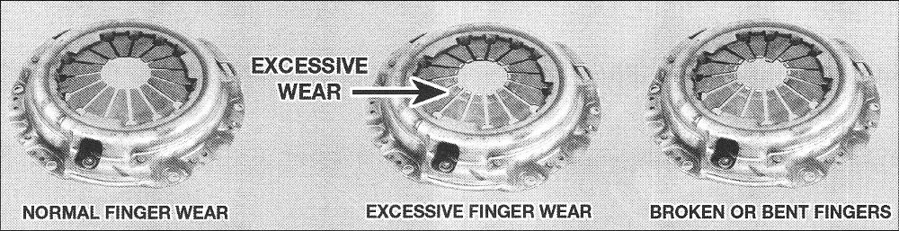
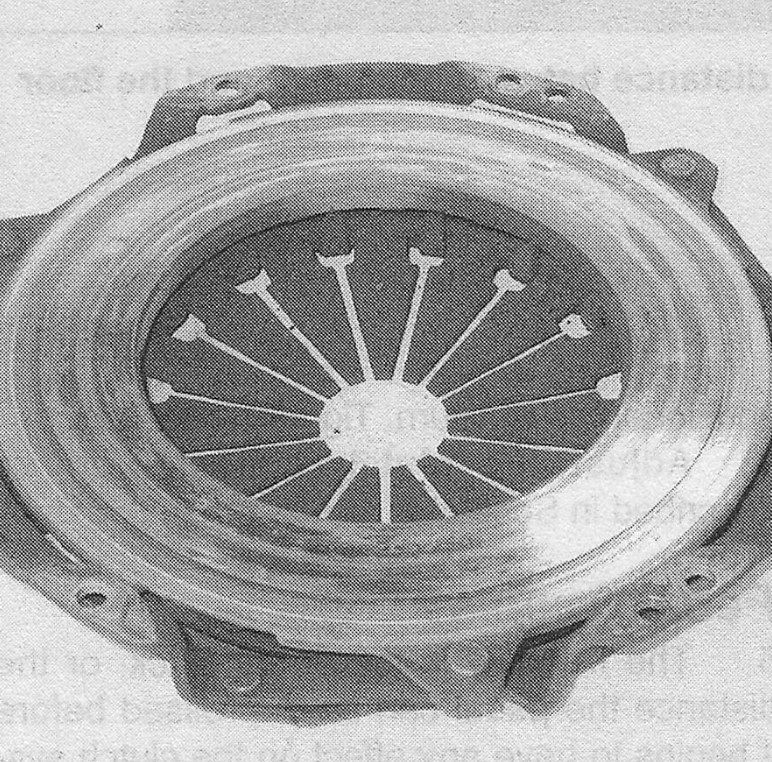
11. Check the machined surfaces and the diaphragm spring fingers of the pressure plate (see illustrations). If the surface is grooved or otherwise damaged, replace the pressure plate. Also check for obvious damage, distortion, cracking, etc. Light glazing can be removed with emery cloth or sandpaper. If a new pressure plate is required, new and re-manufactured units are available.
i.11a Replace the pressure plate if excessive wear or damage is noted
i.11b Inspect the pressure plate surface for excessive score marks, cracks and signs of overheating
Pilot bushing replacement
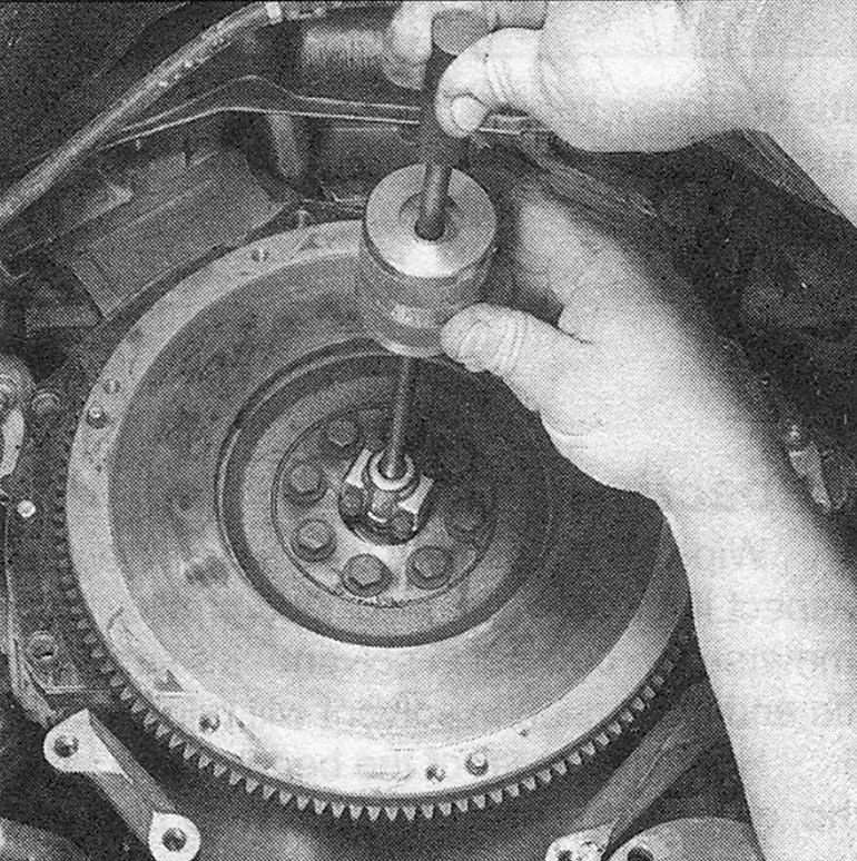
12. Remove the pilot bushing using a slide hammer and puller attachment (see illustration), which are available at most auto parts stores or tool rental yards.
i.12 A small slide hammer is handy for removing a pilot bushing
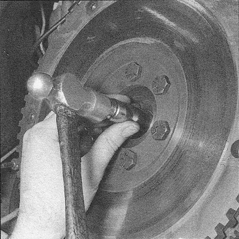
13. To install a new pilot bushing, lightly lubricate the outside surface with grease, then drive it into the recess with a bearing driver or a socket (see illustration).
i.13 Tap the bushing into place with a bearing driver or a socket that is slightly smaller than the outside diameter of the bearing
Installation
14. Before installation, clean the flywheel and pressure plate machined surfaces with brake cleaner. It’s important that no oil or grease is on these surfaces or on the lining of the clutch disc. Handle the parts only with clean hands.
15. Position the clutch disc and pressure plate against the flywheel. Use a clutch alignment tool to hold the clutch in place (see illustration). Make sure the disc is installed properly (most replacement clutch discs will be marked «flywheel side» or something similar — if not marked, install the clutch disc with the damper springs toward the transaxle).
i.15 Center the clutch disc in the pressure plate with a clutch alignment tool

16. Align the indexing marks on the pressure plate and flywheel then insert the pressure plate-to-flywheel bolts but only finger tight, working around the pressure plate.
17. Center the clutch disc by ensuring the alignment tool extends through the splined hub and into the pilot bearing in the crankshaft. Wiggle the tool up, down or side-to-side as needed to center the disc. Tighten the pressure plate-to-flywheel bolts a little at a time, working in a crisscross pattern to prevent distorting the cover. After all of the bolts are snug, tighten them to the torque listed this Chapter’s Specifications. Remove the alignment tool.
18. Using high-temperature grease, lubricate the inner groove of the release bearing (see Clutch release bearing and lever — removal, inspection and installation). Also place a small amount of grease on the release lever contact areas and the transaxle input shaft bearing retainer.
19. Install the clutch release bearing (see Clutch release bearing and lever — removal, inspection and installation).
20. Install the transaxle and all components removed previously.