Driveaxles — removal and installation
Front
Removal
1. Loosen the front wheel lug nuts, raise the vehicle and support it securely on jack stands. Remove the wheel.
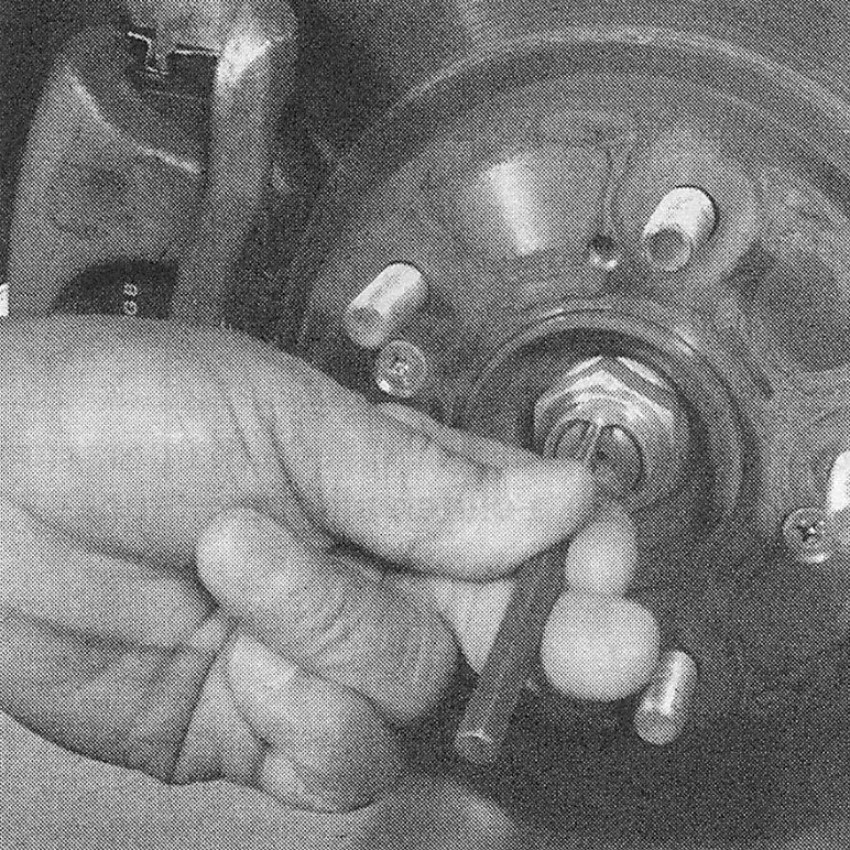
2. Unstack the drive axle/hub nut with a punch or chisel (see illustration).
i.2 Use a punch or chisel and unstack the drive axle/hub nut
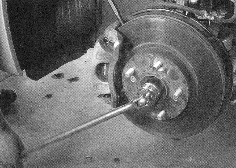
3. Loosen the drive axle/hub nut with a large socket and breaker bar (see illustration), then remove the drive axle/hub nut from the axle and discard it.
i.3 To prevent the hub from turning while you’re loosening the drive axle/hub nut, wedge a prybar or punch into the slots in the brake disc
4. Separate the ballpoint from the control arm (see Suspension and steering).
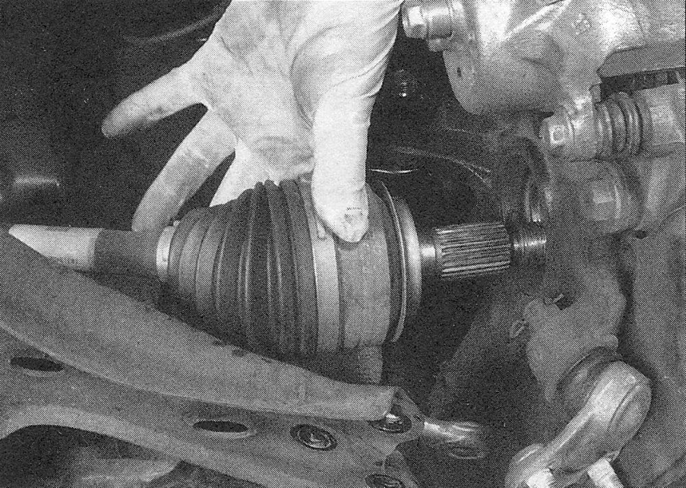
5. Swing the knuckle/hub assembly out (away from the vehicle) until the end of the drive axle is free of the hub. Support the outer end of the drive axle with a piece of wire to avoid unnecessary strain on the inner CV joint (see illustration).
i.5 Swing the steering knuckle out to free the outer end of the drive axle
Note: If the drive axle splines stick in the hub, tap on the end of the drive axle with a plastic hammer.
6. Remove the engine lower splash shield (see 1.8L single overhead camshaft (SOHC) engine, illustrations .3a and .3b)
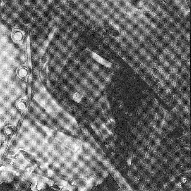
7. Place a drain pan under the transaxle where you are working to catch any oil that may run out. Pry the inner CV joint out of the transaxle (or, on models so equipped, the intermediate shaft) using a large screwdriver or prybar (see illustration).
i.7 Use a large screwdriver or a prybar to pop the inner end of the drive axle from the transaxle or intermediate shaft
Caution: Avoid pulling on the drive axle to remove it or the inner CV joint could come apart. Pry the inner CV joint straight out to prevent damage to the seal.
8. Support the CV joints and carefully remove the drive axle from the vehicle.
Installation
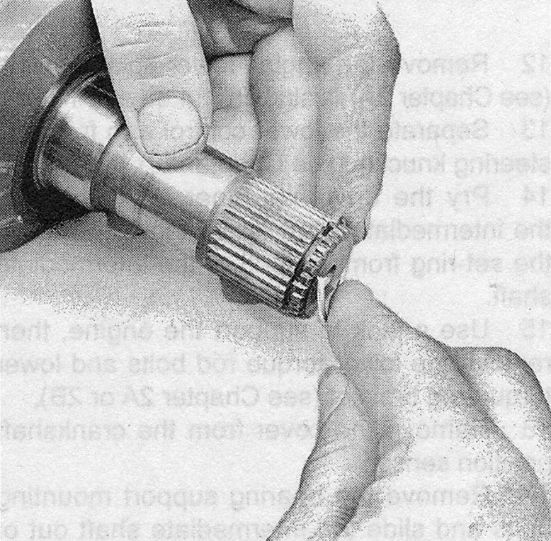
9. Pry the old spring clip from the inner end of the drive axle (or, on models so equipped, the outer end of the intermediate shaft) and install a new one (see illustrations).
i.9a Pry the old spring clip from the
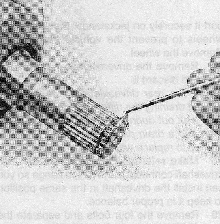
i.9b to install the new spring clip, start one end in the groove and work the clip over the shaft end, into the groove
10. Installation is the reverse of removal, noting the following:
- ) Apply a film of multi-purpose grease around the splines of the joints.
- ) When installing the drive axle, hold the drive axle straight out, then push it in sharply to seat the drive axle spring clip.
- ) Clean all foreign matter from the drive-axle outer CV joint threads and coat the splines with multi-purpose grease. Guide the drive axle into the hub splines and install the new drive axle/hub nut. Tighten the nut securely but not to the specified torque at this time.
- Reconnect the ballpoint to the control arm, then tighten the fasteners to the torque listed in the Suspension and steering Specifications.
- ) Tighten the drive axle/hub nut to the torque listed in this Chapter’s Specifications.
- ) Install the wheel and lug nuts, then lower the vehicle.
- ) Tighten the wheel lug nuts to the torque listed in the Tune-up and routine maintenance Specifications.
- ) Add transaxle lubricant if it was drained or if any fluid spilled out (see Tune-up and routine maintenance).
Intermediate shaft Removal
11. Loosen the right front wheel lug nuts, raise the vehicle and support it securely on jack stands. Remove the wheel.
12. Remove the engine lower splash shield (see 1.8L single overhead camshaft (SOHC) engine, illustrations 14.3a and 14.3b).
13. Separate the lower control arm from the steering knuckle (see Suspension and steering).
14. Pry the drive axle inner CV joint from the intermediate shaft (see Step 7). Remove the set-ring from the end of the intermediate shaft.
15. Use a jack to support the engine, then remove the lower torque rod bolts and lower torque rod bracket (see 1.8L single overhead camshaft (SOHC) engine or 2B).
16. Remove the cover from the crankshaft position sensor.
17. Remove the bearing support mounting bolts and slide the intermediate shaft out of the transaxle. Be careful not to damage the transaxle seal when pulling the shaft out.
18. Check the support bearing for smooth operation by turning the shaft while holding the bearing. If you feel any roughness, take the intermediate shaft to an automotive machine shop or other qualified repair facility to have a new bearing installed.
Installation
19. Install a new spring clip on the end of the intermediate shaft.
20. Lubricate the lips of the transaxle seal with multi-purpose grease. Carefully guide the intermediate shaft into the transaxle side gear then install the mounting bolts for the bearing support. Tighten the bolts to the torque listed in this Chapter’s Specifications.
21. The remainder of installation is the reverse of removal.
Rear (4WD CR-V models) Removal
22. Remove the wheel cover or hub cap. Loosen the wheel lug nuts. Untaken the drive axle/hub nut with a punch or chisel (see illustration 10.2),
then break the hub nut loose with a socket and large breaker bar.
23. Raise the rear of the vehicle and support it securely on jack stands. Block the front wheels to prevent the vehicle from rolling. Remove the wheel.
24. Remove the drive axle/hub nut from the axle and discard it.
Note: The rear drive axles can be removed without draining the differential fluid but some may leak out during the process. Have some rags and a drain pan ready as well as some new oil to replace what was lost.
25. Make reference marks where the rear driveshaft connects to the pinion flange so you can install the driveshaft in the same position to keep it in proper balance.
26. Remove the four bolts and separate the rear driveshaft from the rear pinion flange. Do not allow the driveshaft to hang by the center support bearing, use a loop of wire to suspend the driveshaft out of the way.
27. Disconnect the electrical connectors and the multiple breather hoses from the rear differential housing.
28. Use a transmission jack or floor jack to support the rear differential housing.
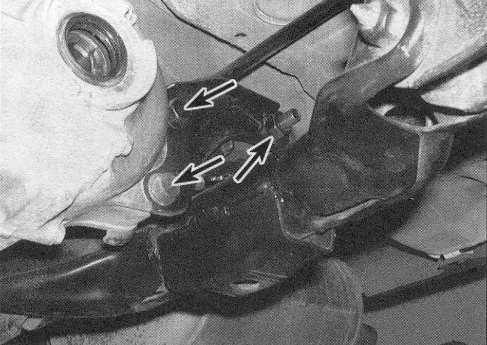
29. Remove and discard the fasteners from the left and right differential mounting brackets (see illustration).
i.29 Differential mounting bracket bolts
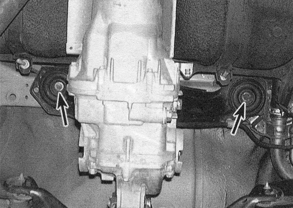
30. Remove the two bolts and their circular plates that fasten the upper differential mounting bracket to the floor pan (see illustration).
i.30 Upper differential bracket-to-floor pan bolts
31. Slowly lower the jack while ensuring that all wire and hose connections are disconnected. As the differential lowers out of the vehicle, pry the left and right inner CV joints from the differential housing, being careful not to damage the CV joints or the differential housing.
32. Pull on the outer CV joint to remove it from the rear hub, being careful not to damage the wheel speed sensor. If the splines are stuck in the rear hub, use a plastic hammer to tap the drive axle out. Do not pull on the drive-axle or the outer joint may come apart.
Installation
33. Pry the old set-ring from the inner end of the drive axle and install a new one (see illustrations 10.8a and 10.8b).
34. Apply a light film of grease to the outer CV joint splines and insert the outer end of the drive axle into the hub.
35. Apply a light film of grease to the area on the inner CV joint stub shaft where the seal rides. Raise the differential and insert the splined end of both inner CV joints into the differential. Make sure the spring clips lock into place.
36. The remainder of installation is the reverse of removal, noting the following:
37. When installing the upper differential bracket to the floor pan, rotate the circular plates to align with the tabs on the rubber bushings. Note that the heat insulator, if equipped, is installed on the right side.
38. Use all new fasteners when installing the left and right differential mounting brackets. Install the brackets on the differential housing first and tighten to the specified torque. Then install but do not tighten the bolts securing the brackets to the frame. Lower the jack then tighten the bolts to the specified torque.
39. Install a new drive axle/hub nut. Tighten the hub nut securely, but don’t try to tighten it to the actual torque specification until you’ve lowered the vehicle to the ground.
40. Install the wheel and lug nuts, then lower the vehicle. Tighten the lug nuts to the torque listed in the Tune-up and routine maintenance Specifications.
41. Tighten the drive axle/hub nut to the torque listed in this Chapter’s Specifications, then use a hammer and a punch to stake the collar of the nut into the slot in the drive axle. Install the wheel cover or hub cap.
42. Check the differential lubricant, adding as necessary to bring it to the appropriate level (see Tune-up and routine maintenance). Use a new sealing washer on the fill plug.