Valve clearance check and adjustment
Check
1. Valve clearances generally do not need adjustment unless valvetrain components have been replaced, a valve job has been performed, or the valvetrain is noisy.
2. The simplest check for proper valve adjustment is to listen carefully to the engine running with the hood open. If the valvetrain is noisy, adjustment is necessary.
Adjustment
3. The valve clearance must be checked and adjusted with the engine cold.
4. Remove the valve cover (see 1.8L single overhead camshaft (SOHC) engine or 2.4L double overhead camshaft (DOHC) engines).
SOHC engines
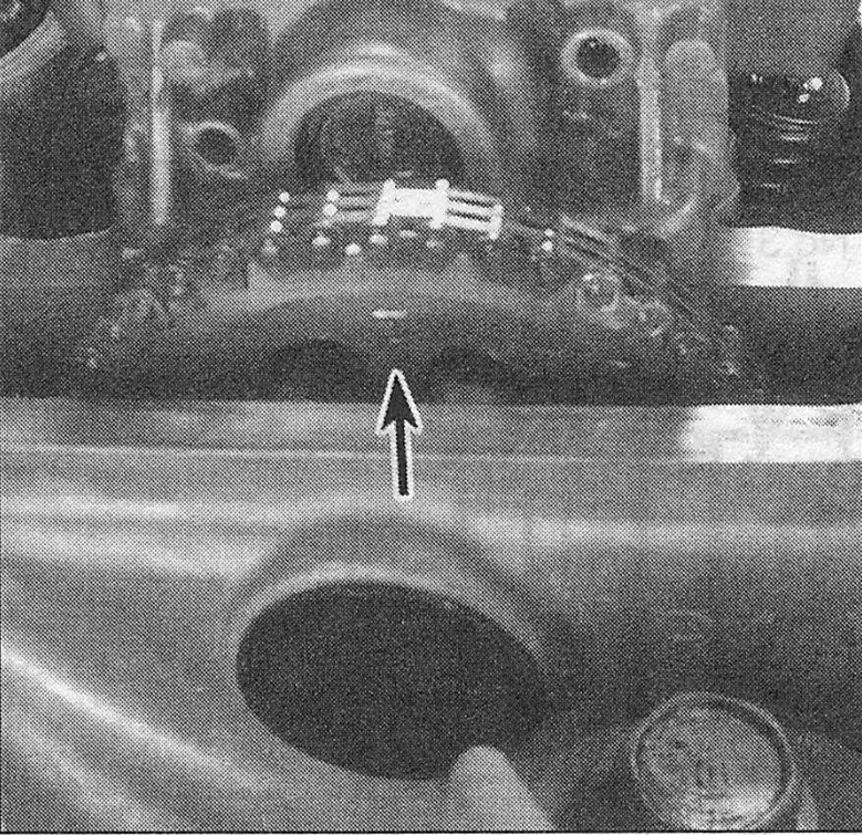
5. Place the number one piston (closest to the drivebelt end of the engine) at Top Dead Center (TDC) on the compression stroke. This is accomplished by rotating the crankshaft in the normal direction of rotation (which is clockwise) until the white TDC mark on the crankshaft pulley aligns with the timing pointer on the timing chain cover and the UP mark on the camshaft sprocket is at the twelve o’clock position (see accompanying illustration and 1.8L single overhead camshaft (SOHC) engine).
i.5 When the engine is at TDC for cylinder number 1, the «UP» mark on the camshaft sprocket will be visible, and the two lines on the sprocket will be parallel with the machined surface of the cylinder head
6. With the engine in this position, the number one-cylinder valve adjustment can be checked and adjusted (see illustration).
i.6 Valve layout (1.8L SOHC engine)
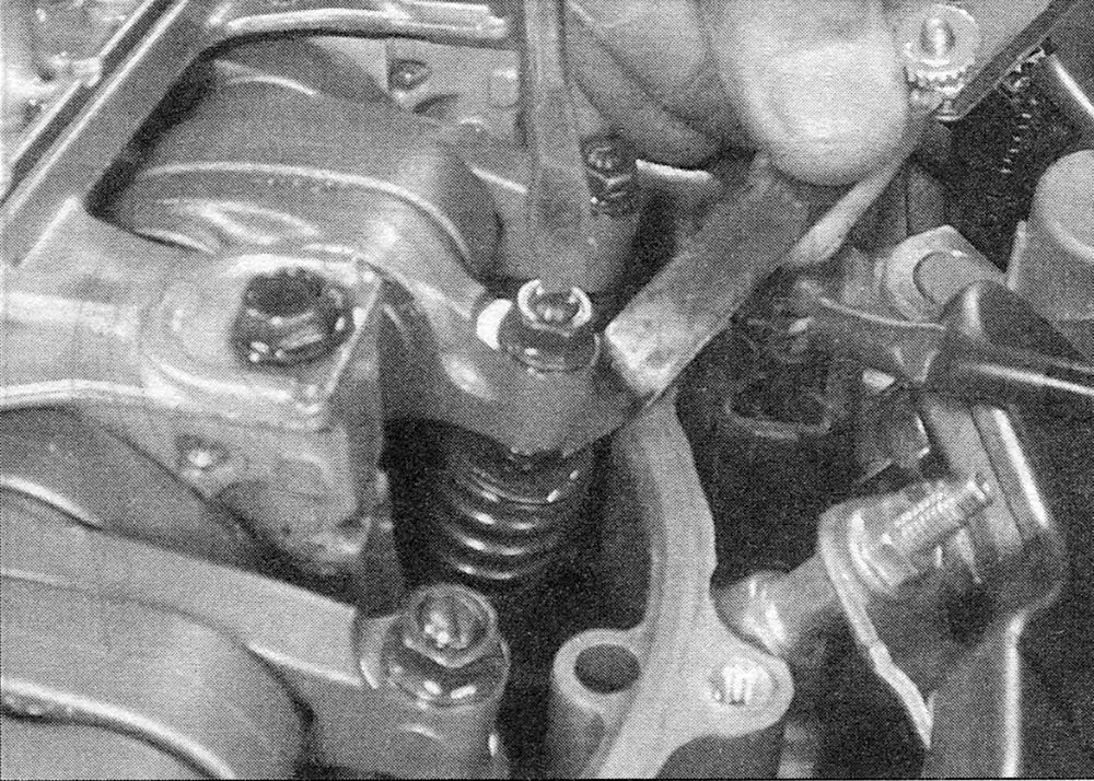
7. Start with the intake valve clearance. Insert a feeler gauge of the correct thickness (see this Chapter’s Specifications) between the valve stem and the rocker arm (see illustration). Withdraw it; you should feel a slight drag. If there’s no drag or a heavy drag, loosen the adjuster nut and back off the adjuster screw. Carefully tighten the adjuster screw until you can feel a slight drag on the feeler gauge as you withdraw it.
i.7 When the adjustment is correct, you will feel a slight drag as you pull the feeler gauge
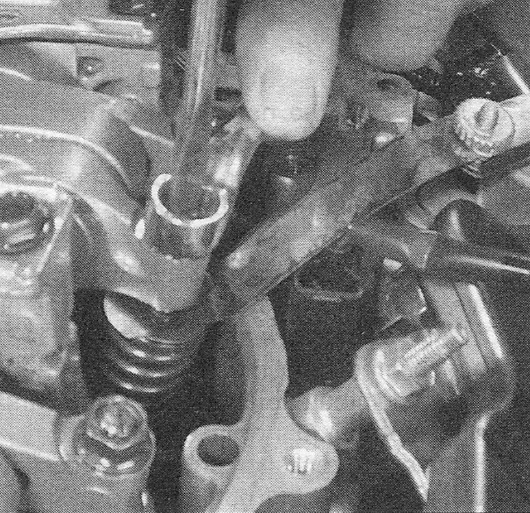
8. Hold the adjuster screw with a screw- driver (to keep it from turning) and tighten the locknut (see illustration). Recheck the clearance to make sure it hasn’t changed. Repeat the procedure in this Step and the previous Step on the other intake valve, then on the two exhaust valves.
i.8 Hold the adjuster screw stationary with the screwdriver while you tighten
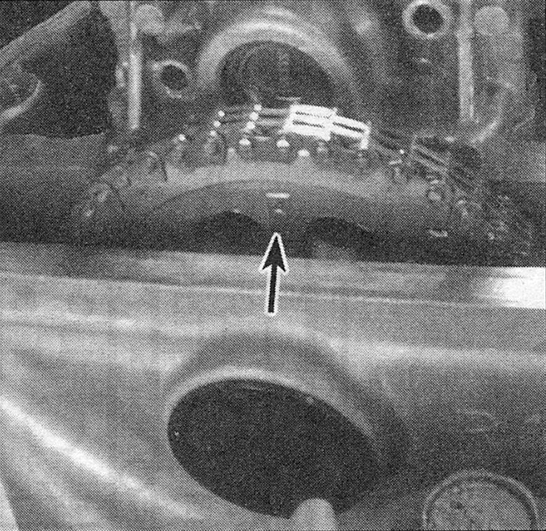
9. Rotate the crankshaft pulley 180-degrees clockwise (the camshaft pulley will turn 90-degrees) until the number three cylinder is at TDC (see illustration). Check and adjust the number three-cylinder valves.
i.9 When the number 3 cylinder is at TDC, the «3» mark will appear at 12 o’clock and the machined line on the cam sprocket will be parallel with the cylinder head surface
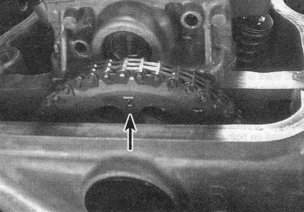
10. Rotate the crankshaft pulley 180-degrees clockwise until the number four cylinder is at TDC (see illustration). Check and adjust the number four-cylinder valves.
i.10 When the number 4 cylinder is at TDC, the «4» mark will appear at 12 o’clock and the machined line on the cam sprocket will be parallel with the cylinder head surface
11. Rotate the crankshaft pulley 180-degrees clockwise to bring the number two cylinder to TDC (see illustration). Check and adjust the number twocylinder valves.
i.11 When the number 2 cylinder is at TDC, the «2» mark will appear at 12 o’clock and the machined line on the cam sprocket will be parallel with the cylinder head surface
12. Install the valve cover (see 1.8L single overhead camshaft (SOHC) engine).
DOHC engines
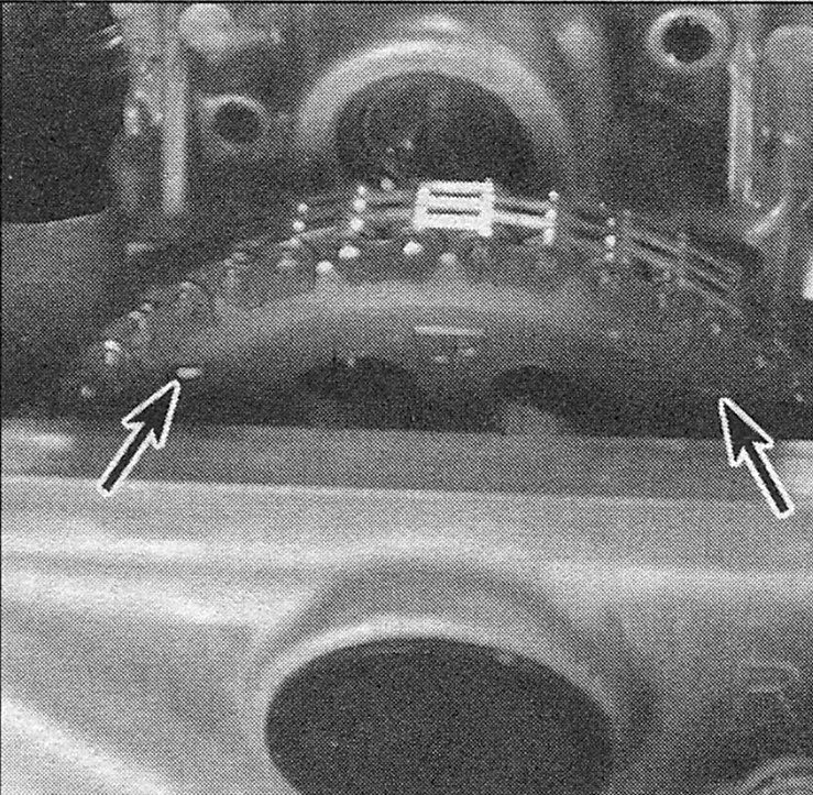
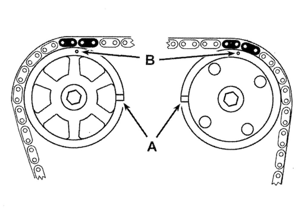
13. Place the number one piston (closest to the drivebelt end of the engine) at Top Dead Center (TDC) on the compression stroke. This is accomplished by rotating the crankshaft in the normal direction of rotation (which is clockwise) until the white TDC mark on the crankshaft pulley aligns with the timing pointer on the lower timing belt cover (see Top Dead Center TDC) for number one piston — locating). The punch marks on the camshaft sprockets should be at the twelve o’clock position and the TDC marks aligned on both sprockets (see illustration).
i.13 When the engine is at TDC for cylinder no. 1, the mark on the crankshaft pulley must be aligned with the pointer on the
timing chain cover, the TDC marks on the camshaft sprockets (A) must be pointing towards each other and the dimples on the sprockets (B) must be pointing UP
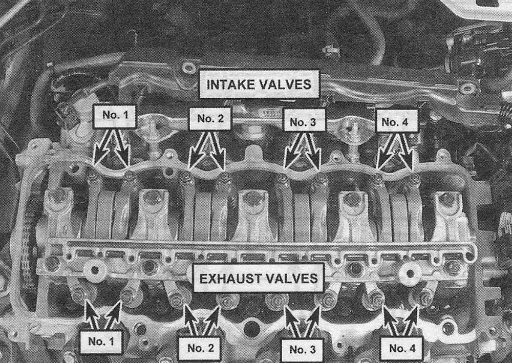
14. With the engine in this position, the number one cylinder valve adjustment can be checked and adjusted (see illustrations).
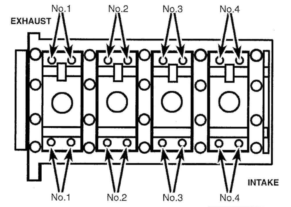
i.14a 2014 and earlier 2.4L DOHC engine valve layout
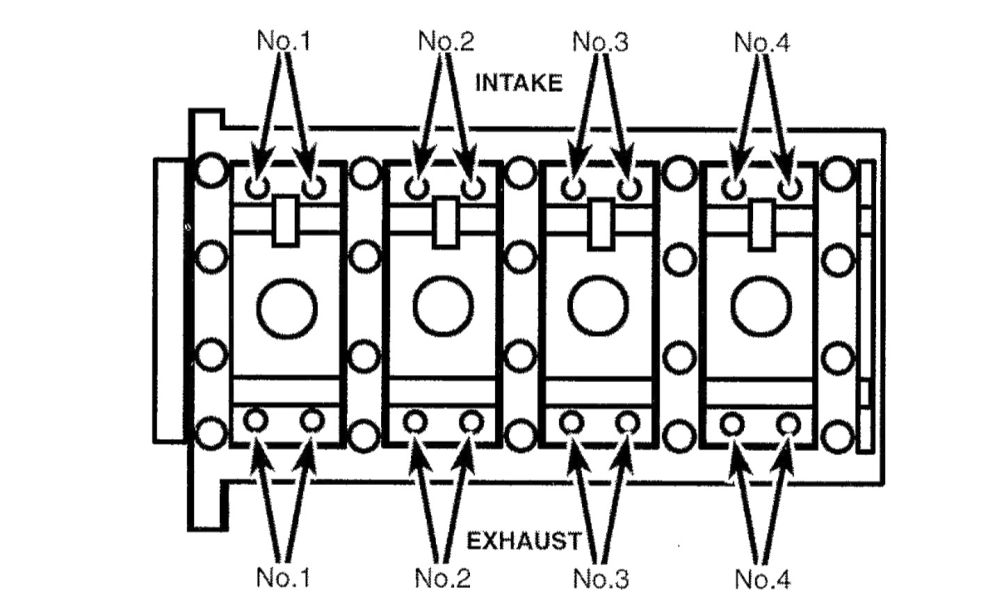
i.14b 2015 and later 2.4L DOHC engine valve layout
15. Start with the intake valve clearance. Insert a feeler gauge of the correct thickness (see this Chapter’s Specifications) between an intake valve stem and the rocker arm. Withdraw it; you should feel a slight drag. If there’s no drag or a heavy drag, loosen the adjuster nut and back off the adjuster screw. Carefully tighten the adjuster screw until you can feel a slight drag on the feeler gauge as you withdraw it (see illustration 23.7).
16. Hold the adjuster screw with a screwdriver (to keep it from turning) and tighten the locknut (see illustration 23.8). Recheck the clearance to make sure it hasn’t changed. Repeat the procedure in this Step and the previous Step on the other intake valve, then on the two exhaust valves.
17. Rotate the crankshaft pulley 180-degrees clockwise (the camshaft pulley will turn
90. degrees) until the number three cylinder is at TDC. With the number three cylinder at TDC, the punch marks on the camshaft sprockets will be at the three o’clock position. Check and adjust the number three-cylinder valves.
18. Rotate the crankshaft pulley 180-degrees clockwise until the number four cylinder is at TDC. With the number four cylinder at TDC, the punch marks on the camshaft sprockets will be pointed straight down. Check and adjust the number four-cylinder valves.
19. Rotate the crankshaft pulley 180-degrees clockwise to bring the number two cylinder to TDC. The punch marks on the camshaft sprockets will be at the nine o’clock position. Check and adjust the number two-cylinder valves.
20. Install the valve cover (see 2.4L double overhead camshaft (DOHC) engines).


