Power brake booster — removal and installation
Operating check
1. Depress the brake pedal several times with the engine off and make sure there is no change in the pedal reserve distance.
2. Depress the pedal and start the engine. If the pedal goes down slightly, operation is normal.
Airtightness check
3. Start the engine and turn it off after one or two minutes. Depress the brake pedal several times slowly. If the pedal goes down farther the first time but gradually rises after the second or third depression, the booster is airtight.
4. Depress the brake pedal while the engine is running, then stop the engine with the pedal depressed. If there is no change in the pedal reserve travel after holding the pedal for 30 seconds, the booster is airtight.
Removal
5. Power brake booster units should not be disassembled. They require special tools not normally found in most automotive repair shops. They are fairly complex and because of their critical relationship to brake performance it is best to replace a defective booster unit with a new or rebuilt one.
6. Remove the brake master cylinder (see Master cylinder — removal and installation).
7. Disconnect the hose leading from the engine to the booster. Be careful not to damage the hose when removing it from the booster fitting.
8. Detach the brake lines from the clamp on the cowl. On CR-V models, remove the engine wiring harness clamp bolts and reposition the harness.
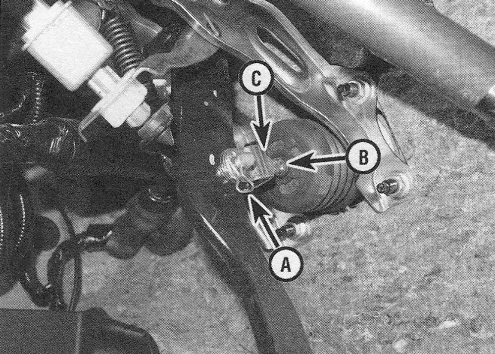
9. Locate the pushrod clevis pin connecting the booster to the brake pedal (see illustration). Remove the clevis pin retaining clip with pliers and pull out the pin.
i.9 Remove the clevis pin retaining clip (A) and clevis pin, then disconnect the pushrod clevis from the pedal. (B) is the pushrod and (C) is the pushrod locknut
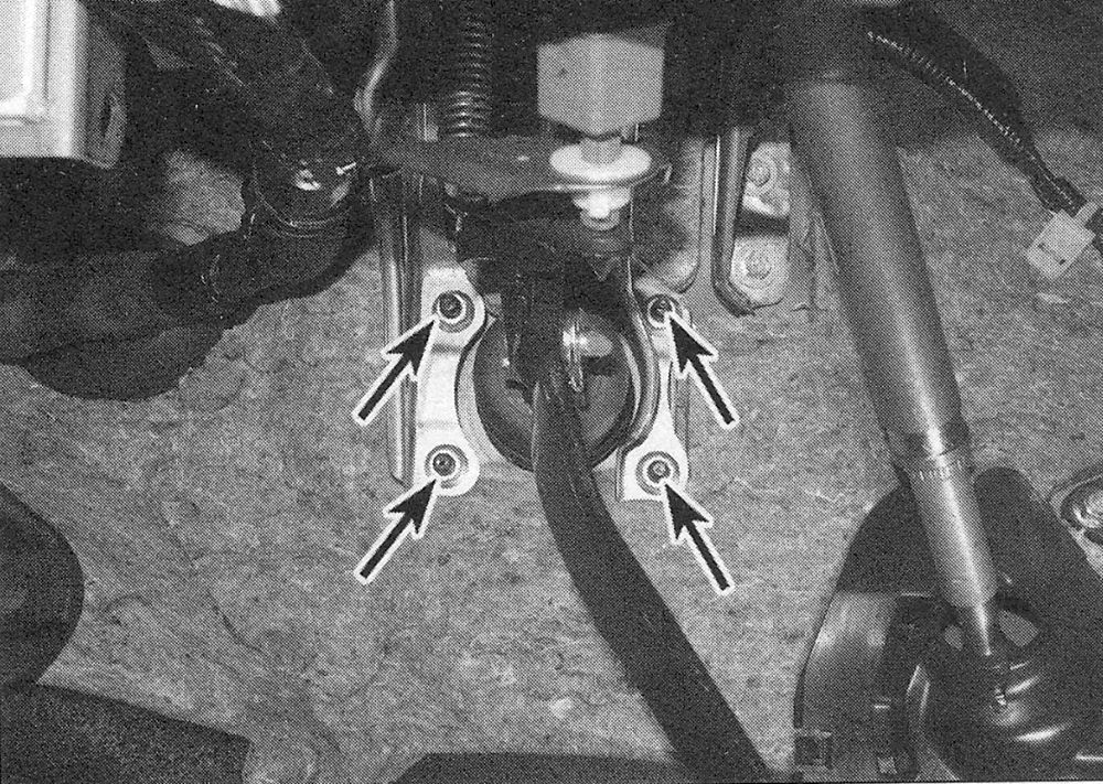
10. Remove the four nuts (see illustration) holding the brake booster to the firewall.
i.10 Remove the four booster mounting nuts
11. Slide the booster straight out from the firewall until the studs clear the holes and pull the booster, brackets and gaskets from the engine compartment area.
Installation
12. Installation procedures are the reverse of those for removal. Tighten the booster mounting nuts to the torque listed in this Chapter’s Specifications. Also, be sure to use a new cotter pin on the clevis pin.
13. Install the master cylinder and bleed it (see Master cylinder — removal and installation), followed by the rest of the brake system (see Brake hydraulic system — bleeding).
14. Check and, if necessary, adjust, the brake pedal height and free play (see Brake pedal — adjustment).