Stabilizer bar and bushings (front) — removal, inspection and installation
Removal
1. Loosen the front wheel lug nuts, raise the front of the vehicle and support it securely on jack stands. Apply the parking brake and block the rear wheels to keep the vehicle from rolling off the stands. Remove the front wheels.
Stabilizer bar links
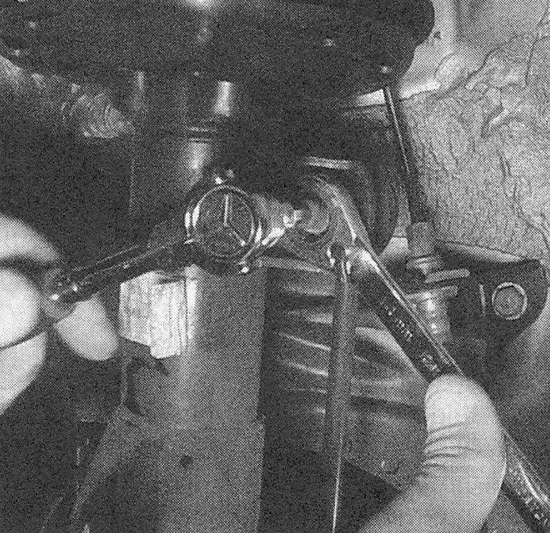
2. Remove the nuts securing the stabilizer bar links to the control arms and the stabilizer bar (see illustration).
i.2 Use an Allen wrench to prevent the stabilizer bar link ball stud from turning when removing the nut
3. Detach the link from the bar and control arm.
4. Installation is the reverse of removal. Tighten the nuts to the torque listed in this Chapter’s Specifications.
Stabilizer bar and bushings
5. Working in the driver’s footwell, remove the steering column joint cover, then detach the steering column shaft from the steering gear (see Steering gear — removal and installation).
Caution: Don’t allow the steering wheel to turn after the shaft has been disconnected from the steering gear — the airbag clock spring could be damaged. To prevent this from happening, run the seat belt through the steering wheel and click it into its latch. Also, don’t allow the slip joint of the shaft to become disengaged from the upper portion of the shaft; if necessary, restrain it with a length of wire.
6. Detach the stabilizer bar links from the control arms as described previously in this Section.
7. Detach the ballpoints from the steering knuckles (see Control arm (front) — removal and installation).
8. Detach the tie-rod end from the steering knuckle (see Tie-rod ends — removal and installation).
9. Remove under-vehicle splash shields (see 1.8L single overhead camshaft (SOHC) engine, illustrations 14.3a and 14.3b)
10. Remove front section of the exhaust system (see Fuel and exhaust systems).
CR-V models
11. If you’re working on an AWD model, remove the driveshaft (see Clutch and driveline).
12. Support the rear of the subframe with a floor jack. Remove the rear subframe bolts and the mid (center) subframe bolts, and loosen the front subframe bolts approximately 1-3/16 inches (30 mm).
13. Remove the torque rod (roll restrictor)- to-engine bolts.
14. Lower the subframe approximately 5-18 inches (130 mm).
Civic models
15. Remove the steering gear fasteners (see Steering gear — removal and installation).
16. Remove the steering gear stiffener brackets, if equipped (see Steering gear — removal and installation).
All models
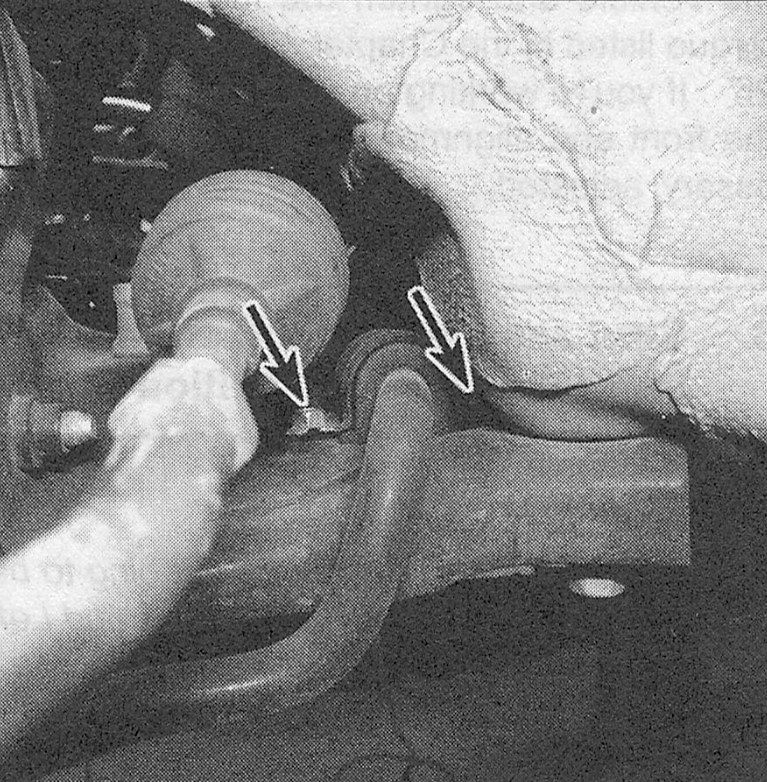
17. Remove the stabilizer bar brackets bolts and brackets (see illustration).
i.17 Stabilizer bar bracket bolts
18. If you’re working on a Civic model, lift up on the steering box a few inches and hold it in place while you slide the stabilizer bar out the driver’s side of the vehicle.
Note: When reinstalling the rubber bushings for the stabilizer bar be sure to have the slits in the bushing in the same direction as they previously were.
Inspection
19. Inspect for cracked, torn, or distorted stabilizer bar bushings, bushing retainers, and worn or damaged stabilizer bar links.
20. To replace damaged stabilizer bar bushings, remove the bracket (if not already done), open the bushing slit and peel the bushing from the stabilizer bar. On some models, it will be necessary to bend back the tabs holding the retainer together.
Caution: Install the new bushings with the slits facing the same way that the original bushing slits faced.
Installation
21. Guide the stabilizer bar into position. Install the bushing bracket bolts, tightening them to the torque listed in this Chapter’s Specifications.
22. On CR-V models, raise the subframe and install the bolts, tightening them to the torque listed in this Chapter’s Specifications. Install the torque rod bolts, tightening them to the torque listed in the Chapter 2.4L double overhead camshaft (DOHC) engines Specifications.
23. Connect the stabilizer bar links to the lower control arms. Tighten the nuts to the torque listed in this Chapter’s Specifications.
24. Connect the ball joints to the control arms, tightening the nuts to the torque listed in this Chapter’s Specifications.
25. Install the wheels and lug nuts. Lower the vehicle and tighten the lug nuts to the torque listed in the Tune-up and routine maintenance Specifications.
26. If you’re working on a CR-V model, have the front-end alignment checked and, if necessary, adjusted.